Chapter 7: Leaf-Spine Fabric
This chapter describes a leaf-spine switching fabric implemented by a collection of control applications. We use SD-Fabric, running on ONOS, as our exemplar implementation. Various aspects of SD-Fabric were introduced in earlier chapters, so we summarize those highlights before getting into the details.
SD-Fabric supports the leaf-spine fabric topology that is commonly used to interconnect multiple racks of servers in a datacenter (see Figure 10), but it also supports multi-site deployments (see Figure 17). SD-Fabric uses only bare-metal switches, equipped with the software described in the previous chapters, to build out the fabric. It can run on a mix of fixed-function and programmable pipelines but is running in production with the former.
SD-Fabric supports a wide range of L2/L3 features, all re-implemented as SDN control apps (with the exception of a DHCP server used to relay DHCP requests and a Quagga BGP server used to exchange BGP routes with external peers). SD-Fabric implements L2 connectivity within each server rack and L3 connectivity between racks.
SD-Fabric supports access/edge networking technologies, such as PON (see Figure 13) and RAN (see Figure 17), including support for (a) routing IP traffic to/from devices connected to those access networks and (b) off-loading access network functionality into the fabric switches.
This chapter does not give a comprehensive description of all of these features, but it does focus on the datacenter fabric use case, which is sufficient to illustrate the approach to building a production-grade network using SDN principles. More information about the full range of SD-Fabric design decisions is available on the SD-Fabric website.
Further Reading
SD-Fabric. Open Networking Foundation, 2021.
7.1 Feature Set
SDN provides an opportunity to customize the network, but for pragmatic reasons, the first requirement for adoption is to reproduce functionality that already exists and do so in a way that reproduces (or improves upon) the resilience and scalability of legacy solutions. SD-Fabric has satisfied this requirement, which we summarize here.
First, with respect to L2 connectivity, SD-Fabric supports VLANs, including native support for forwarding traffic based on VLAN id, along with Q-in-Q support based on an outer/inner VLAN id pair. Support for Q-in-Q is particularly relevant to access networks, where double tagging is used to isolate traffic belonging to different service classes. In addition, SD-Fabric supports L2 tunnels across the L3 fabric (both single- and double-tagged).
Second, with respect to L3 connectivity, SD-Fabric supports IPv4 and IPv6 routing for both unicast and multicast addresses. For the latter, SD-Fabric implements centralized multicast tree construction (as opposed to running a protocol like PIM) but does include IGMP support for end hosts wishing to join/leave multicast groups. SD-Fabric also supports both ARP (for IPv4 address translation) and NDP (for IPv6 neighbor discovery), along with support for both DHCPv4 and DHCPv6.
Third, SD-Fabric provides high availability in the face of link or switch failures. It does this through a combination of well-known techniques: dual-homing, link binding, and ECMP link groups. As illustrated in Figure 39, each server in an SD-Fabric cluster is connected to a pair of Top-of-Rack (ToR, or leaf) switches, where the OS running on each compute server implements active-active link bonding. Each leaf switch is then connected by a pair of links to two or more spine switches, with an ECMP group defined for the pair of links connecting each leaf to a given spine and for the set of links connecting each leaf to a set of spines. The cluster as a whole then has multiple connections to external routes, shown via leaf switches 3 and 4 in the Figure. Not shown in Figure 39 is the fact that SD-Fabric runs on top of ONOS, which is itself replicated for the sake of availability. In a configuration like the one shown here, ONOS (and hence the SD-Fabric control applications) are replicated on three to five servers.
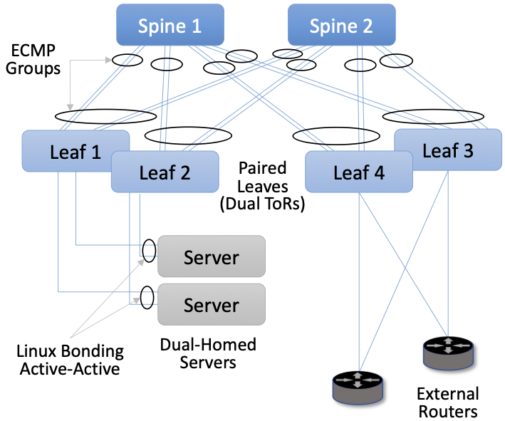
Figure 39. High availability through a combination of dual-homing, link bonding, and ECMP groups.
The use of link aggregation and ECMP is straightforward: the packet forwarding mechanism is augmented to load-balance outgoing packets among a group (e.g., a pair) of links (egress ports) rather than having just a single “best” output link (egress port). This both improves bandwidth and results in an automatic recovery mechanism should any single link fail. It is also the case that switch forwarding pipelines have explicit support for port groups, so once equivalences are established, they can be pushed all the way into the data plane.
To be clear, ECMP is a forwarding strategy that SD-Fabric applies uniformly across all the switches in the fabric. The SD-Fabric control application knows the topology and pushes the port groups into each of the fabric switches accordingly. Each switch then applies these port groups to its forwarding pipeline, which then forwards packets across the set of ports in each group without additional control plane involvement.
Fourth, with respect to scalability, SD-Fabric has demonstrated the ability to support up to 120k routes and 250k flows. This is in a configuration that includes two spine switches and eight leaf switches, the latter implying up to four racks of servers. As with availability, SD-Fabric’s ability to scale performance is directly due to ONOS’s ability to scale.
7.2 Segment Routing
The previous section focused on what SD-Fabric does. This section focuses on how. The core strategy in SD-Fabric is based on Segment Routing (SR). The term “segment routing” comes from the idea that the end-to-end path between any pair of hosts can be constructed from a sequence of segments, where label-switching is used to traverse a sequence of segments along an end-to-end path. Segment routing is a general approach to source routing which can be implemented in a number of ways. In the case of SD-Fabric, segment routing leverages the forwarding plane of Multi-Protocol Label Switching (MPLS), which you can read more about online.
Further Reading
Multi-Protocol Label Switching. Computer Networks: A Systems Approach, 2020.
When applied to a leaf-spine fabric, there are always two segments involved: leaf-to-spine and spine-to-leaf. SD-Fabric programs the switches to match labeled or unlabeled packets and push or pop MPLS labels as needed. Figure 40 illustrates how SR works in SD-Fabric using a simple configuration that forwards traffic between a pair of hosts: 10.0.1.1 and 10.0.2.1. In this example, the servers connected to Leaf 1 are on subnet 10.0.1/24, the servers connected to Leaf 2 are on subnet 10.0.2/24, and each of the switches has an assigned MPLS id: 101, 103, 102, and 104.
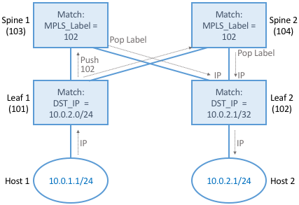
Figure 40. Example of Segment Routing being used to forward traffic between a pair of hosts.
When Host 1 sends a packet with destination address 10.0.2.1, it is by default forwarded to the server’s ToR/leaf switch. Leaf 1 matches the destination IP address, learns this packet needs to cross the fabric and emerge at Leaf 2 to reach subnet 10.0.2/24, and so pushes the MPLS label 102 onto the packet. Because of ECMP, Leaf 1 can forward the resulting packet to either spine, at which point that switch matches the MPLS label 102, pops the label off the header, and forwards it to Leaf 2. Finally, Leaf 2 matches the destination IP address and forwards the packet along to Host 2.
What you should take away from this example is that SR is highly stylized. For a given combination of leaf and spine switches, SD-Fabric first assigns all identifiers, with each rack configured to share an IP prefix and be on the same VLAN. SD-Fabric then pre-computes the possible paths and installs the corresponding match/action rules in the underlying switches. The complexity having to do with balancing load across multiple paths is delegated to ECMP, which is similarly unaware of any end-to-end paths. From an implementation perspective, the SD-Fabric control application that implements SR passes these match/action rules to ONOS, which in turn installs them on the underlying switches. SD-Fabric also maintains its own Atomix map to manage the set of ECMP groups connecting leaf and spine switches.
7.3 Routes and Multicast
In addition to Segment Routing, which establishes data paths between leaf switches, SD-Fabric also takes advantage of the Route and Mcast services introduced in Chapter 6. They determine which of the leaf-spine switches serve each IP prefix and where to find all the hosts connected to each multicast group, respectively.
SD-Fabric does not run distributed protocols like OSPF to learn about routes or PIM to construct multicast trees. Instead, it computes the right answers based on global information and then pushes these mappings to the Route and Mcast services. This is straightforward to do because SD-Fabric imposes the simplifying constraint that each rack corresponds to exactly one IP subnet.
To make this discussion more concrete, consider that all the ONOS
Services described in Chapter 6 can be invoked via a RESTful API, or
alternatively, through a CLI that is a thin wrapper around REST’s
GET, POST, and DELETE calls. Using the CLI to illustrate
(because it is easier to read), one can query the Route service to
learn the existing routes as follows:
onos> routes

B: Best route, R: Resolved route

Table: ipv4
B R  Network            Next Hop        Source (Node)
     0.0.0.0/0          172.16.0.1      FPM (127.0.0.1)
> *  1.1.0.0/18         10.0.1.20       STATIC
> *  10.0.99.0/24       10.0.1.1        FPM (127.0.0.1)
  *  10.0.99.0/24       10.0.6.1        FPM (127.0.0.1)
   Total: 2

Table: ipv6
B R  Network                   Next Hop                  Source (Node)
> *  2000::7700/120            fe80::288:ff:fe00:1       FPM (127.0.0.1)
> *  2000::8800/120            fe80::288:ff:fe00:2       FPM (127.0.0.1)
> *  2000::9900/120            fe80::288:ff:fe00:1       FPM (127.0.0.1)
  *  2000::9900/120            fe80::288:ff:fe00:2       FPM (127.0.0.1)
   Total: 3
Similarly, one can add a static route to the Route Service:
onos> route-add <prefix> <nexthop>
onos> route-add 1.1.0.0/18 10.0.1.20
onos> route-add 2020::101/120 2000::1
One thing to note about these examples is that there are two possible
sources for routes. One is that the route is STATIC, which usually
means that SD-Fabric inserted it with full knowledge of the what prefix
it has assigned to each rack in the cluster. (Human operators could
also add a STATIC route using the CLI, but this would be an
exception rather than the rule.)
The second possibility is that FPM was the source. FPM (Forwarding
Plane Manager) is yet
another ONOS Service–one of the SD-Fabric suite of services. Its
job is to learn routes from external sources, which it does by tapping
into a locally running Quagga process that is configured to peer with
BGP neighbors. Whenever FPM learns about an external route, it adds
the corresponding prefix-to-nexthop mapping to the Route service,
indicating that the destination prefix is reachable via the leaf
switches that connect the fabric to upstream networks (e.g., Switches 3
and 4 in Figure 39).
The story with multicast is similar. Again using the ONOS CLI, it is possible to create a new multicast route and add a sink to it. For example:
onos> mcast-host-join -sAddr *
    -gAddr 224.0.0.1
    -srcs 00:AA:00:00:00:01/None
    -srcs 00:AA:00:00:00:05/None
    -sinks 00:AA:00:00:00:03/None
    -sinks 00:CC:00:00:00:01/None
specifies Any-Source Multicast (ASM) (sAddr *), a multicast group address
(gAddr), the group source addresses (srcs), and the group sink
addresses (sinks). A sink can then be removed as follows:
onos> mcast-sink-delete -sAddr *
    -gAddr 224.0.0.1
    -h  00:AA:00:00:00:03/None
Again, there is no PIM running, but instead, SD-Fabric offers a programmatic interface for network operators to define a multicast tree through a sequence of such calls. For example, when SD-Fabric runs as part of an access network that delivers IPTV to subscribers, one option is for software running on the operator’s set-top boxes to issue calls similar to those shown above (except, of course, using the RESTful API rather than the CLI). Another option is to have set-top boxes send IGMP messages, which SD-Fabric intercepts using the Packet Service (similar to how the Host service intercepts ARP and DHCP packets). So the next time you use your TV remote to change channels, you may be triggering procedure invocations up and down the SDN software stack described throughout this book!
7.4 Customized Forwarding
SD-Fabric is an example use case for SDN. It is a set of control applications running top of a Network OS, which in turn runs on top of a collection of programmable switches arranged in a leaf-spine topology, where each switch runs a local Switch OS. In this way, SD-Fabric serves as a capstone for our bottom-up tour of the SDN software stack.
But if we knew from the outset that a leaf-spine fabric supporting the
SD-Fabric feature-set was exactly what we wanted, we might go back to
lower layers and tailor them for that purpose. This is what has
happened over time with SD-Fabric, resulting in a customized forwarding
plane implemented by a P4 program called fabric.p4. We conclude
this chapter by giving a high-level summary of fabric.p4,
highlighting how its design meshes with the rest of the software
stack.
Before doing that, it is important to acknowledge that knowing exactly
what you want from a network at the outset is an impossibly high
bar. Networks evolve based on experience using and operating them. No
one knew how to write fabric.p4 on day one, but after iterating
through a series of implementations of the other layers up-and-down
the stack (including the introduction of Tofino as a programmable
forwarding pipeline), fabric.p4 emerged. The point is that
treating the network as a programmable platform frees you to
continually and rapidly evolve it.
Said another way, we introduced forward.p4 as our canonical
example of “a forwarding plane customized to do exactly what we want”
in Chapter 4, but then spent the rest of the chapter describing all
the machinery that makes something like forward.p4 possible,
without ever revisiting what network-specific functionality it might
actually implement. In short, fabric.p4 is a specific example of
forward.p4, which we are only now able to describe because of how
it relates to the control plane.
There are three things of note about fabric.p4. First, it is
loosely based on the Broadcom OF-DPA pipeline, which makes sense
because SD-Fabric was originally implemented on top of a set of
Tomahawk-based switches. The fabric.p4 pipeline is simpler than
OF-DPA, as it eliminates tables that SD-Fabric does not need. This makes
fabric.p4 easier to control.
Second, fabric.p4 is designed to mimic ONOS’s FlowObjective API,
thereby simplifying the process of mapping FlowObjectives onto
P4Runtime operations. This is best illustrated by Figure 41, which shows fabric.p4's ingress pipeline. The
egress pipeline is not shown, but it is a straightforward rewriting of
the header fields in the common case.
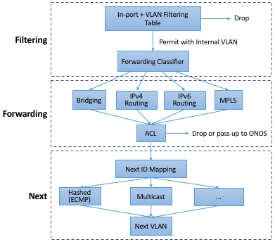
Figure 41. Logical pipeline supported by fabric.p4, designed to parallel
the Filtering, Forwarding, and Next stages of the FlowObjective
API.
Third, fabric.p4 is designed to be configurable, making it
possible to selectively include additional functionality. This is not
easy when writing code that is optimized for an ASIC-based forwarding
pipeline; in practice, it makes heavy use of pre-processor
conditionals (i.e., #ifdefs). The code fragment shown below is the
main control block of fabric.p4's ingress function. Chapter 9
discusses these optional extensions in more depth but at a high
level:
UPF (User Plane Function): Augments IP functionality in support of 4G/5G Mobile Networks.
BNG (Broadband Network Gateway): Augments IP functionality in support of Fiber-to-the-Home.
INT (Inband Network Telemetry): Adds metric collection and telemetry output directives.
apply {
#ifdef UPF
    upf_normalizer.apply(hdr.gtpu.isValid(), hdr.gtpu_ipv4,
	hdr.gtpu_udp, hdr.ipv4, hdr.udp, hdr.inner_ipv4,
	hdr.inner_udp);
#endif // UPF

    // Filtering Objective
    pkt_io_ingress.apply(hdr, fabric_metadata, standard_metadata);
    filtering.apply(hdr, fabric_metadata, standard_metadata);
#ifdef UPF
    upf_ingress.apply(hdr.gtpu_ipv4, hdr.gtpu_udp, hdr.gtpu,
	hdr.ipv4, hdr.udp, fabric_metadata, standard_metadata);
#endif // UPF

    // Forwarding Objective
    if (fabric_metadata.skip_forwarding == _FALSE) {
        forwarding.apply(hdr, fabric_metadata, standard_metadata);
    }
    acl.apply(hdr, fabric_metadata, standard_metadata);

    // Next Objective
    if (fabric_metadata.skip_next == _FALSE) {
        next.apply(hdr, fabric_metadata, standard_metadata);
#if defined INT
        process_set_source_sink.apply(hdr, fabric_metadata,
	    standard_metadata);
#endif // INT
    }
#ifdef BNG
    bng_ingress.apply(hdr, fabric_metadata, standard_metadata);
#endif // BNG
}
For example, a companion file, upf.p4 (not shown), implements the
forwarding plane for the UPF extension, which includes the GTP tunnel
encapsulation/decapsulation required by the 3GPP cellular standard to
connect the SD-Fabric fabric to the base stations of the Radio Access
Network. Similarly, bng.p4 (not shown) implements PPPoE
termination, which is used by some Passive Optical Networks
deployments to connect the SD-Fabric fabric to home routers. Finally,
it is worth noting that the code fragment illustrates the basic
structure of fabric.p4's core functionality, which first applies
the filtering objective (filtering.apply), then applies the
forwarding objective (forwarding.apply and acl.apply), and
finally applies the next objective (next.apply).
In addition to selecting which extensions to include, the pre-processor also defines several constants, including the size of each logical table. Clearly, this implementation is a low-level approach to building configurable forwarding pipelines. Designing higher-level language constructs for composition, including the ability to dynamically add functions to the pipeline at runtime, is a subject of ongoing research.