Chapter 8: Network Virtualization
As noted in Chapter 2, Network Virtualization was the first commercially successful use case of SDN. That said, it sits somewhat apart from the rest of SDN described in this book. This is because network virtualization can be implemented on the servers, generally without any cooperation from the switches in the physical network. The fact that network virtualization can be implemented as an overlay on an existing network was a great help in terms of deployment. At the same time, this ease of deployment meant that it left the physical network untouched, thus not really impacting the level of innovation in physical networks. It did, however, result in considerable simplification in how physical networks are managed, as this chapter illustrates.
Virtualization is an established concept in computer science that goes back decades. That applies to network virtualization as well. Virtual private networks (VPNs), for example, were implemented using Frame Relay and ATM networks in the 1990s, and virtual LANs (VLANs) became part of the Ethernet standards in the late 1990s. These technologies did not have much in common with SDN, but instead were implemented using conventional networking technologies. Importantly, they did not separate the control and data planes in the manner that is considered fundamental to SDN.
The application of SDN to create virtual networks is generally credited to the team at Nicira, as discussed in Chapter 2, with a 2014 paper by Koponen et al. laying out the architecture of an SDN-based system to implement network virtualization.
Further Reading
T. Koponen et al. Network Virtualization in Multi-tenant Datacenters. NSDI, April, 2014.
The following sections show how a particular set of technology challenges, combined with the new capabilities offered by SDN, set the stage for network virtualization as a successful use case of Software-Defined Networking.
8.1 Challenges
Network virtualization as we understand it today is closely linked to the evolution of modern datacenters, in which large numbers of commodity servers communicate with each other to solve computational tasks. These datacenters are common for both large cloud providers (e.g., AWS, Azure, Google), as well as many enterprise organizations. Some of the challenges involved in building networks for such datacenters were laid out in the VL2 paper from Microsoft Research back in 2009.
Further Reading
Greenberg et al. VL2: a scalable and flexible data center network. SIGCOMM, August, 2009.
In such datacenters, there is a substantial amount of “east-west” traffic; that is, server-to-server traffic, as distinct from “north-south” traffic entering or leaving the datacenter. To efficiently support high volumes of traffic between any pair of servers in the datacenter, leaf-spine fabrics of the sort described in Chapter 7 became popular due to their high cross-sectional bandwidth and scalable layer-3 forwarding.
At the same time, server virtualization became mainstream, which had several implications for datacenter operations. Provisioning virtual machines (VMs) can be carried out entirely in software, by contrast to installing and configuring physical servers, a time-consuming and manual process. As the ease of provisioning a VM shrank the time to obtain computational resources from days to minutes or seconds, it exposed the fact that network configuration was now the “long pole”—the slowest task to be completed before a user could put their infrastructure to work. Hence, there was a recognition that network configuration and provisioning needed to move towards a model more similar to virtual compute, setting the stage for network virtualization.
A second effect of server virtualization was to enable virtual machine mobility. This introduced some real challenges for datacenter networking. In the absence of network virtualization, the IP address of a VM is drawn from the physical network on which it resides, and must be specific to a subnet that connects to the server hosting the VM.1 So if a VM is to migrate to another server, either it needs to move to a server where that subnet is also present, or it needs a new IP address. The first choice limits where it can move within the datacenter, which affects the efficiency of resource usage. The second option is quite a disruptive thing: TCP connections are dropped, and applications may need to be restarted. Furthermore, some applications depend on layer-2 adjacency between communicating peers, and thus depend on some set of VMs staying in a given subnet even as they move around within the datacenter.
- 1
Technically more than one subnet can connect to a given server in which case an IP address for a VM needs to be drawn from one of those subnets.
One proposed solution to this issue was to make layer-2 subnets ever larger in the physical network, but that is not really a scalable solution. Large datacenters invariably use layer-3 networking to connect racks of servers.
The approach proposed by Greenberg, et al. can be considered a first step in network virtualization. They created a Virtual Layer 2 (VL2) network such that the addresses used by virtual machines are decoupled from the addresses used in the physical network, thus solving the mobility-related issues described above. A VM draws its IP address from a virtual layer 2 network, and VL2 constructs the appropriate overlay to extend that virtual network wherever it needs to go, even as VMs migrate across physical networks.
Solving the problem of network configuration is a bit more complex. Networks are not just simple subnets to connect servers; they have a host of features that need to be configured, including VLANs (or some equivalent construct to segment the network), firewall rules, network address translation (NAT) rules, and so on. It is the complexity of these tasks that made network configuration the barrier to agility in datacenter configuration.
Tackling these issues of configuration and provisioning ultimately led to the realization that SDN provided a means to simplify the creation and management of virtual networks, just as much as it simplifies the operation of physical networks. The key insight is that a central API to an SDN controller provides the ideal way to specify the desired behavior of the virtual network, with the central controller then taking responsibility for figuring out how to implement the network with the available resources, such as virtual switches in the hypervisors of the datacenter’s servers. The core principles of SDN—separation of data plane from control plane, and centralization of the controller to manage a multitude of switching elements—provide the basis for this approach. The coming sections dig deeper into how this works.
8.2 Architecture
The simplest possible network virtualization system is shown in Figure 42. Virtual switches reside at end hosts, and virtual machines connect to those virtual switches. The network virtualization controller exposes a northbound API that receives inputs describing the intended state of a virtual network. For example, an API request could specify “VM1 and VM2 should reside on the same virtual layer 2 subnet, network X”. It is the responsibility of the controller to determine where those virtual machines are located, and then to send control commands to the appropriate virtual switches to create the virtual network abstraction that is required. Let’s look more closely at that abstraction.
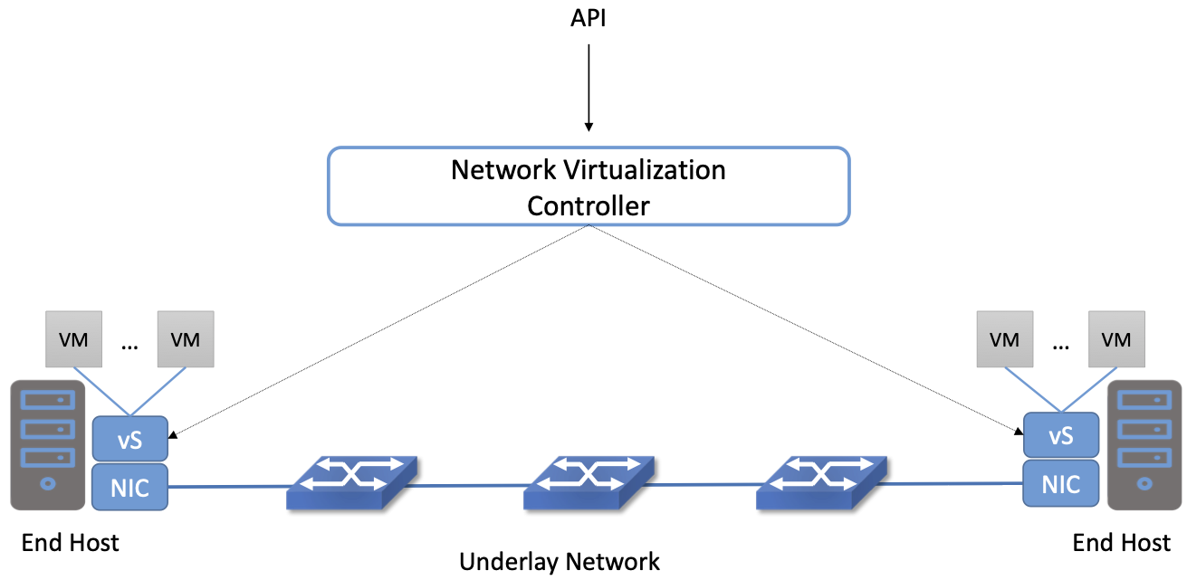
Figure 42. A Basic Network Virtualization System.
Since the VMs should be free to move around the datacenter, their IP addresses need to be independent of the physical network topology (indicated by the underlay network in the figure). In particular, we don’t want a particular VM to be restricted in its location by the subnet addressing of the underlying physical network. For this reason, network virtualization systems invariably make use of an overlay encapsulation such as VXLAN or NVGRE. Encapsulation is a low-level mechanism that solves an important problem: decoupling the address space of the virtual network from that of the physical network. However, it is worth noting that they are just a building block, and not a complete network virtualization solution. We will look more closely at network virtualization overlay encapsulations in Section 8.3.1.
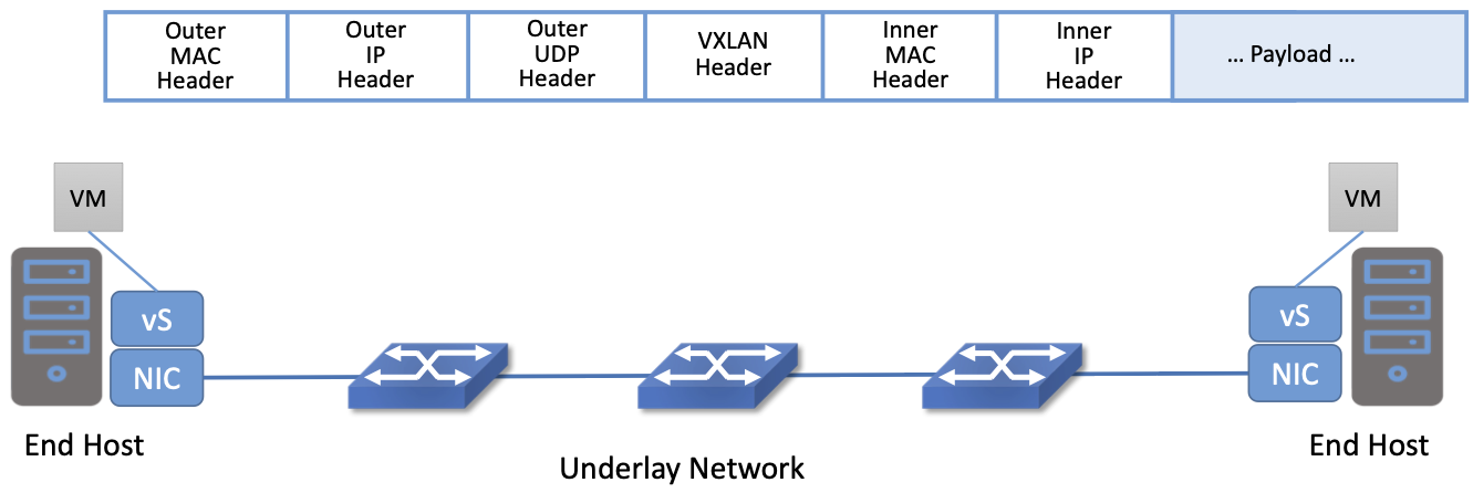
Figure 43. Encapsulation decouples virtual network addresses from physical network.
One thing to notice about virtual network encapsulation, as illustrated in Figure 43, is that there are a set of outer headers that are used by the physical network to deliver the packet to the appropriate end host, and there are a set of inner headers that are meaningful only in the context of a particular virtual network. This is how encapsulation decouples the virtual network addressing from that of the physical.
This simple example also shows one of the tasks that must be implemented by the network virtualization controller. When a VM wants to communicate with one of its peers in a virtual network, it needs to apply the appropriate outer header, which is a function of the current server location of the VM. Providing the mapping from target VM to outer header is a natural task for the centralized controller. In VL2 this is referred to as a directory service.
To better understand the functions of the network virtualization controller, we need to look a bit more closely at the definition of a virtual network.
8.2.1 Virtual Networks Defined
As noted above, the idea of virtual networks goes back a long way. Virtual LANs (VLANs), for example, allow multiple LAN segments to co-exist on a single physical LAN, somewhat analogous to the way virtual memory allows processes to share physical memory. However, the vision for virtual networks, as laid out by the Nicira team in the NSDI paper, is more closely analogous to virtual machines.
Virtual machines provide a faithful reproduction of the features of a physical server, complete with processor, memory, peripherals, and so on. The reproduction is so complete that an unmodified operating system can run on the virtual machine exactly as if it were running on a physical machine.
By analogy, virtual networks must also reproduce the full feature set of a physical network. This means that a virtual network includes routing, switching, addressing, and higher layer features such as NAT, firewalling, and load balancing. Just as an unmodified operating system can run on a VM exactly as it would on a physical machine, an unmodified distributed application should be able to run on a virtual network exactly as it would on a physical network. This is clearly a more elaborate proposition than a VLAN.
Importantly, a virtual network needs to keep operating correctly even as VMs move around. Thus, we can begin to see that the role for a network virtualization controller is to accept a specification of the desired virtual network and then ensure that this network is correctly implemented on the appropriate resources as conditions change and VMs move. We formalize this role for the controller in the next section.
8.2.2 Management, Control, and Data Planes
We can now look more closely at the basic architecture of a network virtualization system. In contrast to early types of virtual networks such as VLANs and VPNs, a modern network virtualization system exposes a northbound API by which virtual networks are created and managed. Through calls to this API, the topology and services of a virtual network are specified—either by a human user or by another piece of software such as a cloud automation platform. Typical API requests might say “Create a layer 2 subnet”, “Attach VM A to subnet X” or “Apply firewall policy P to traffic entering VM B”. As shown in Figure 44, these API requests lead to the creation of desired state—the state that the network should be in. It is common to refer to the part of the system that receives API requests and stores them in a desired state database as the management plane.
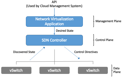
Figure 44. The Three Planes of a Network Virtualization System.
At the bottom of Figure 44 is the data plane. Commonly, this is a set of Virtual Switches (vSwitches) that run inside hypervisors or container hosts. The data plane is where virtual networks are implemented. As we saw in the example, a virtual switch forwards packets between VMs and the physical network, and to do it needs to apply appropriate headers to the packets. The data plane also has information about the current state of the system, such as the locations of VMs, that needs to be taken into account by the higher layers of the network virtualization system. This is indicated by the discovered state.
At the heart of the system is the control plane. It sits between the desired state and the actual state of the system. As the control plane receives discovered state information from the data plane, it compares this against the desired state. If the desired state does not match the actual state, the control plane calculates the necessary changes and pushes them to the data plane, as indicated by the control directives arrow. This paradigm, of continuously reconciling actual state with desired state, is a common one in distributed systems.
The mapping between this architecture (Figure 44) and the one depicted in Figures 15 and 16 in Chapter 3 is straightforward. At the base is a distributed data plane, be it assembled from bare-metal switches or software switches, on top of which a centralized controller collects operational state and issues control directives. When implemented in a general, use-case agnostic way, this controller is called a Network OS. The Nicira team built an early network OS called Onix, which can be thought of as a precursor of ONOS. At the top-most level is a management layer that serves API requests, and understands the abstraction of a virtual network. This management layer can be thought of as an application that runs on the network OS. In short, the architecture presented in this Chapter is purpose-built to support virtual networks, whereas the one outlined in Chapter 3 is intended to be general-purpose, and in fact, there was at one time an ONOS-based virtual network application, called Virtual Tenant Network (VTN), that was integrated with OpenStack. VTN is no longer being maintained, due in part to the availability of other network virtualization subsystems that integrate with container management systems like Kubernetes.
Consider a simple example. We want to create a virtual network that connects two VMs, A and B, to a single L2 subnet. We can express that intent by a set of API requests; for example, create the subnet, connect A to the subnet, connect B to the subnet. These API requests are accepted by the management plane and stored as desired state. The control plane observes changes in desired state that are not yet reflected in the actual state, so it needs to determine where A and B are located, and the IP addresses of the relevant hypervisors. With this information, it determines what the encapsulation of packets should be if A and B are to communicate with each other. From this, it computes a set of control directives that need to be installed into the appropriate vSwitches. These directive are pushed to the vSwitches, expressed, for example, as a set of OpenFlow rules.
If, at some later time, one of the VMs moves to a different hypervisor, this information is passed to the control plane, which detects that the actual state no longer corresponds to the desired state. That triggers a fresh computation to determine the updates that need to be pushed to the data plane, such as new forwarding rules to the appropriate set of vSwitches, and deletion of data plane state at the hypervisor that no longer hosts one of the VMs.
With this architecture, we can implement a rich set of features for virtual networks. Provided the data plane has sufficient richness to implement forwarding rules for firewalls, load balancers, and so on, it is now possible to build a network virtualization system that accurately recreates the features of a physical network in software.
8.2.3 Distributed Services
Software implementations of network functions such as firewalling, load balancing, and routing are essential aspects of network virtualization. However, it is not simply a matter of implementing a traditional network device in software. Consider the example of a firewall. A conventional firewall is implemented as a choke point: the network is set up in such a way that traffic must pass through the firewall to get from one part of the network to another.
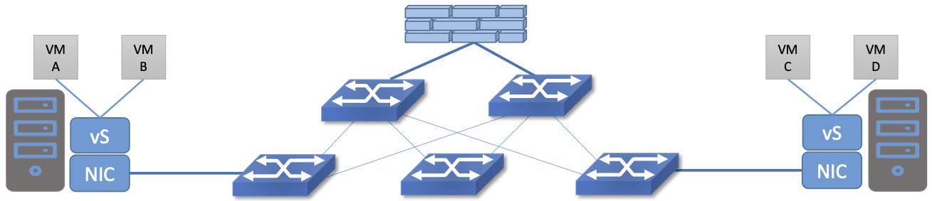
Figure 45. A conventional firewall (not distributed).
Consider the example in Figure 45. If traffic sent from VM A to VM C needs to be processed at a firewall in a conventional network, it needs to be routed over a path that traverses the firewall, not necessarily the shortest path from A to C. In the more extreme case of traffic from VM A to VM B, which sit on the same host, the traffic from A to B needs to be sent out of the host, across the network to the firewall, and then back to B. This is clearly not efficient, and consumes both network resources and, in the latter case, NIC bandwidth for the hairpinned traffic. Furthermore, the firewall itself has the potential to become a bottleneck, as all traffic requiring treatment must pass up to that centralized device.
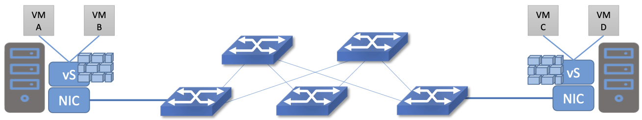
Figure 46. A distributed firewall.
Now consider Figure 46, which illustrates a distributed firewall implementation. In this case, traffic sent from VM A to VM C can be processed by a firewall function at either (or both) of the virtual switches that it traverses, and still be sent over the shortest path through the network underlay between the two hosts, without hairpinning to an external firewall. Furthermore, traffic from VM A to VM B need never even leave the host on which those two VMs reside, passing only through the virtual switch on that host to receive the necessary firewall treatment.
A significant side effect of distributing a service in this way is that there is no longer a central bottleneck. Every time another server is added to host some more VMs, there is a new virtual switch with capacity to do some amount of distributed service processing. This means it is relatively simple to scale out the amount of firewalling (or whatever other service is being delivered) in this way.
This same approach applies to many other services that might formerly have been performed in a dedicated box: routing, load balancing, intrusion detection, and so on. This is not to say that these services are trivial to implement in a distributed manner in all cases. But with a centralized control plane, we are able to provision and configure these services via an API (or a GUI) in one location, and implement them in a distributed manner with the efficiency and performance benefits outlined here.
8.3 Building Blocks
Now that we understand the architecture of network virtualization systems, let’s look at some of the building blocks used to construct such a system.
8.3.1 Virtual Network Encapsulation
As we noted above, network virtualization requires some sort of encapsulation so that the addressing in the virtual network can be decoupled from that of the physical network. Inventing new ways to encapsulate packets seems to be a popular pastime for network architects and engineers, and there were a few potential candidates available already when network virtualization appeared on the scene. None of them quite fit the bill however, and several more have been developed over the last decade.
While VXLAN attracted considerable attention when it was first introduced in 2012, it was by no means the last word in network virtualization encapsulation. After many years of experimentation and collaboration among software and hardware vendors and other IETF participants, an encapsulation that combined most of the desired features was developed and standardized. The following RFC describes GENEVE and the set of requirements that it was developed to meet.
Further Reading
J. Gross, I. Ganga and T. Sridhar (Eds.), Geneve: Generic Network Virtualization Encapsulation (RFC 8926).
A notable feature of GENEVE is its extensibility. This represented something of a compromise between those building software-based systems (such as the one from Nicira) and those building hardware endpoints designed to support network virtualization (which we’ll cover later in this chapter). Fixed headers make life easy for hardware, but limit flexibility for future expansion. In the end, GENEVE included an options scheme that could be efficiently processed (or ignored) by hardware while still giving the required extensibility.

Figure 47. GENEVE Header Format.
As shown in Figure 47, GENEVE looks quite similar to VXLAN, the notable difference being the presence of a set of variable length options. The presence of options was a critical feature that built on the experience of earlier systems, where it was realized that the limited space in a VXLAN header was insufficient to pass metadata related to virtual networks from one end of a tunnel to another. An example use of such metadata is to convey the logical source port of a packet so that subsequent processing of that packet can take its source port into consideration. There is a general point here that, since virtual networks evolve over time with increasingly sophisticated features implemented in software, it is important not to constrain the information that can be passed around inside a virtual network with an overly restrictive packet encapsulation.
8.3.2 Virtual Switches
The Virtual Switch clearly plays a critical role in network virtualization. It is the main component of the data plane, and the richness of its feature set determines the ability of a network virtualization system to accurately reproduce the features of a physical network. The most widely deployed virtual switch is Open vSwitch (OVS).
Further Reading
B. Pfaff, et al, The Design and Implementation of Open vSwitch, USENIX NSDI 2015.
Open vSwitch has been used in proprietary systems such as Nicira’s Network Virtualization Platform and VMware NSX, as well as open source systems such as Open Virtual Network (OVN) described in Section 8.4. It was designed to have the necessary flexibility to meet the requirements of network virtualization while also providing high performance.
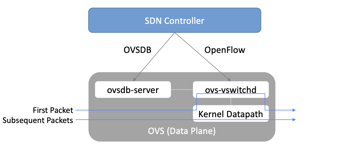
Figure 48. Open vSwitch Functional Blocks.
As depicted in Figure 48, OVS is programmed by the control plane using OpenFlow, just like many hardware switches described in previous chapters. It also receives configuration information over a separate channel using the Open vSwitch Database (OVSDB) protocol, which is to say, OVSDB effectively serves the same purpose as gNMI/gNOI does for a hardware-based data plane. Again, the mapping between these building blocks and the components described in earlier chapters is straightforward, the differences in terminology and details largely being attributed to network virtualization evolving as a purpose-built solution.
OVSDB as depicted in the Figure refers to an RPC protocol used to
access the database (called ovsdb-server), but in general, OVSDB
can refer to either the protocol or the database. As a database, OVSDB
has a schema, which you can think as OVS’s counterpart to the
OpenConfig schema described in Section 5.3. As a protocol, OVSDB uses
a JSON-based message format, analogous to gNMI’s use of protobufs. It
is also worth noting that OVSDB has taken on a life of its own, beyond
the role shown in Figure 48, as a general
way to represent network forwarding state. We’ll see an example of
this broader role in Section 8.4.
As for the OVS data plane, performance has been achieved via a long
series of optimizations described in the Pfaff paper, notably a
fast-path in the kernel that uses a flow cache to forward all packets
in a flow after the first. The first packet in a flow is passed to the
userspace daemon ovs-vswitchd, which looks up the flow in a set of
tables. This set of tables, being implemented in software, can be
effectively unlimited in number, a distinct advantage over hardware
implementations of OpenFlow switching. This enables the high degree of
flexibility that is required in network virtualization. At the same
time, there is also an effort to unify software- and hardware-based
forwarding elements, using P4 as the lingua franca for writing packet
forwarders. This also brings P4Runtime into the mix as the
auto-generated interface for controlling the data plane.
Note that OVS can be used not only to forward packets between VMs and the outside world, but can also be used in container environments, to forward packets among containers on the same or different hosts. Thus a network virtualization system for containers can be built from many of the same components as one for VMs, and mixed environments (where containers and VMs communicate in a single virtual network) are also possible.
8.3.3 Performance Optimizations
Since the virtual switch sits in the data path for all traffic entering or leaving VMs and containers in a virtual network, the performance of the virtual switch is critical. The OVS paper from 2015 discusses a number of performance optimizations made over the years, but approaches to improving vSwitch performance warrant further discussion.
The first is DPDK (Data Plane Development Kit), a set of libraries developed for the Intel x86 platform to improve performance of data-moving operations, including virtual switching. Many of the concepts are straightforward (e.g., packets can be processed in batches, context switches are avoided) but the set of optimizations is large and, when applied properly, effective. It has been successfully used to implement OVS with performance gains that can be significant, depending on the exact operating environment.
One such environment is using OVS to forward packets between a virtual and a non-virtual network, which typically happens when a VM needs to communicate with something outside the virtual network. This could be, for example, an unvirtualized server such as a mainframe or database, or some device on the public Internet. This scenario is referred to as a Virtual-to-Physical Gateway, and it is a good candidate for DPDK because it has little to do other than forward packets (i.e., no other CPU-bound processing is involved). In this setting, experiments reported by RedHat Developer shows OVS-DPDK is able to forward over 16Mpps on a high-end Intel processor. (This is compared to a forwarding rate closer to 1Mpps with OVS alone.)
Further Reading
RedHat Developer. Measuring and Comparing Open vSwitch Performance, June 2017.
The second is SR-IOV (Single Root IO Virtualization), a hardware feature designed to improve IO performance between VMs and the outside world. The basic idea is that a single physical NIC presents itself to the hypervisor as a set of virtual NICs, each of which has its own set of resources. Each VM could then have its own virtual NIC, and bypass the hypervisor completely, which in principle would improve performance. However, this isn’t really a useful approach for network virtualization, because the virtual switch is bypassed. Much of the value of network virtualization comes from the flexibility of a programmable virtual switch, so bypassing it runs counter to the direction of network virtualization.
On the other hand, there is value in recognizing that the NIC has a role to play in the end-to-end story. There is a long tradition of offloading certain functions from the server to the NIC, with TCP Segmentation Offload (TSO) being a notable example. As NICs have gained more capability in recent years with the rise of SmartNICs, the potential exists to move more of the vSwitch capability to the NIC with a potential performance gain. The challenge is in trading flexibility for performance, as SmartNICs are still more resource-constrained than general-purpose CPUs. The latest generation of SmartNICs is reaching a level of sophistication where offloading some or all of the vSwitch functions could be effective.2
- 2
As an aside, P4 is gaining traction as a way to program SmartNICs, suggesting the possibility of convergence in how the data plane—whether implemented as a vSwitch, a SmartNIC, or a bare-metal switch—exports its capabilities to the control plane.
Finally, it is worth noting that even a well-implemented software switch on general-purpose hardware is going to perform relatively poorly compared to a dedicated switching hardware, and for this reason, there have also been implementations of gateways that leverage such bare-metal switches. One example, which took advantage of the VXLAN implementations on many top-of-rack switches, is described in a paper by Davie, et al.
Further Reading
B. Davie, et al. A Database Approach to SDN Control Plane Design. Computer Communications Review, January 2017.
As in many other networking environments, there is a trade-off between the flexibility of fully programmable devices and the performance of less flexible, dedicated hardware. In most commercial deployments of network virtualization, the more flexible approach of general purpose hardware has been preferred. Over time, the trick will be to identify the relatively fixed (but universally applicable) subset of that functionality that provides the biggest performance benefit when implemented in hardware.
8.4 Example System
There have been several successful implementations of network virtualization systems, of which we have already mentioned several. This section describes Open Virtual Network (OVN), a well-documented open source project, as an example of a network virtualization system.
OVN is built as a set of enhancements to OVS, leveraging OVS for the data plane and a set of databases (built on OVSDB) for its control and management planes. The high level architecture of OVN is shown in Figure 49.

Figure 49. OVN High-level Architecture.
An important aspect of OVN is its use of two databases (referred to as Northbound and Southbound) to store state. Theses databases are implemented using OVSDB, which was originally created to store configuration state for OVS, as discussed in Section 8.3.2. In OVN, OVSDB has a larger role, being used for both configuration state and control state.
OVN is assumed to operate in an environment where a Cloud Management
System (CMS) is responsible for the creation of virtual networks. This is
likely to be OpenStack, which was the first CMS to be supported by
OVN. The OVN/CMS plugin is responsible for mapping abstractions that
match those of the CMS into generic virtual network abstractions that
can be stored in the Northbound Database. OVN uses an instance of
ovsdb-server to implement this database. We can think of the plugin as the
management plane and the Northbound DB as the desired state repository.
The control plane of OVN demonstrates a significant novel feature compared to the generic architecture of Figure 44. Importantly, it is divided into a centralized component, known as ovn-northd, and a distributed component that runs on every hypervisor, called the OVN controller. Recall that in Section 1.2.2 we discussed the trade-off between centralized and distributed control for SDN; in OVN, a hybrid model is used. The decision to make this split followed the experience of the OVN team in working on earlier systems where the centralized controller had a full view of all flows, which presented a scaling challenge. OVN retains logically centralized control, so that a single API entry point can be used to create networks, query status, and so on, but distributes out to each hypervisor the control functions related to physical information such as the location of VMs in specific servers. This led to significant gains in the scalability of the system.
A centralized component, ovn-northd,
translates the logical network configuration, expressed in terms of
conventional network concepts like switching and routing, into logical
datapath flows, which it stores in the OVN Southbound
Database. We can see how logical flows work with an example shown in
Figure 50.
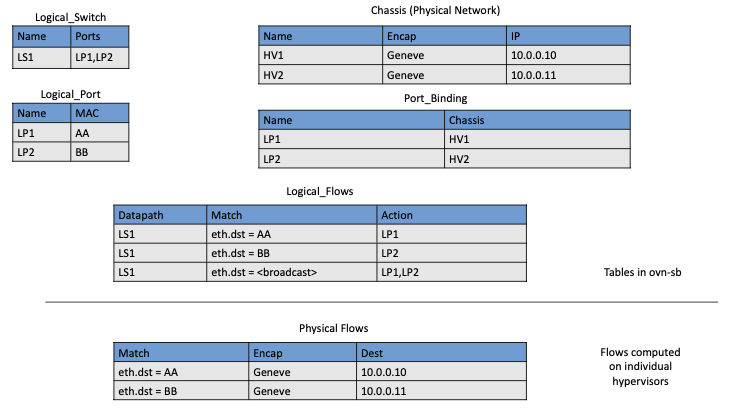
Figure 50. Logical and Physical Flows in OVN.
Logical data path flows provide an abstract representation
of the forwarding rules that are populated in the data
plane, specified in a way that is independent of the physical
location of VMs. In this example, we have created a logical switch
LS1, with two ports, LP1 and LP2. Each port connects to a VM and the
MAC addresses of the VMs are AA and BB as shown in the
Logical_Port table.
The Logical_Flows table, built from the information in the
Logical_Switch and Logical_Port tables, shows how packets are
to be forwarded to implement this logical switch. For example, the
first row indicates that packets destined for a MAC address of AA
need to be sent to port LP1. But there is not enough information
to actually forward packets in this flow, because that depends on
which hypervisors currently host those VMs. Providing the binding of
physical hypervisor nodes to VMs is a task performed by the OVN
controller running on the appropriate hypervisor. This is an example
of discovered state, in the sense that the hypervisors discover the
location of VMs and report it up to the database. So we see that the
controller on HV1 (hypervisor 1) has reported into the Chassis
table that it can be reached using the Geneve encapsulation at IP
address 10.0.0.10. And that same hypervisor has reported into the
Port_Binding table that it is hosting the VM with LP1.
In order to program the data plane, the OVN controller for
each hypervisor queries the OVN Southbound DB to identify the logical
flows that are relevant to it, based on the VMs that it currently
hosts. Combined with the information provided by other hypervisors
regarding the location of other VMs, it is able to construct the rules
that need to be programmed into the instance of OVS running
locally on the hypervisor in question. (Note that the OVS instances
shown in Figure 49 include all the components
shown as part of the OVS data plane in Figure 48.) Continuing with the example above, hypervisor 2 needs a
flow rule in OVS to forward packets from LP2 to LP1. It is able to
see this by looking at the Logical_Flows in OVN Southbound DB, and it
is able to determine the details of how to encapsulate packets and
forward them to the right destination server using information in the
Port_Binding and Chassis tables. You see the results for both
hypervisors in the table at the bottom of the figure, which is not
part of the Southbound DB but is a collation of the flows computed at
the two hypervisors.
You can find a lot more detail on OVN in its online documentation, including descriptions of the structure of the Northbound and Southbound databases.
Further Reading
Open Virtual Network. OVN Reference Guide.
Everything discussed up to this point has assumed that we are talking about VMs as the endpoints for our virtual networks, but everything that works for VMs also works for containers (glossing over some implementation details). We can connect a set of container hosts to the OVN Southbound DB and they can create flow rules for their OVS instances to build virtual networks for the containers they are hosting. In this case, the “cloud management system” that OVN integrates with is likely to be a container management system, such as Kubernetes.
8.5 Microsegmentation
Network virtualization has certainly had an impact on networking, particularly in the datacenter, in the years since Nicira’s first product. Both Cisco and VMware have periodically reported the adoption rates for network virtualization and the technology is now widespread in Telcos and large enterprise datacenters. It is also ubiquitous in the datacenters of large cloud companies, as an essential component of delivering infrastructure as a service.
One of the interesting side-effects of network virtualization is that it enabled a change in the way security is implemented in the datacenter. As noted above, network virtualization enables security features to be implemented in a distributed manner, in software. It also makes it relatively straightforward to create a large number of isolated networks, compared to the traditional approach of configuring VLANs by hand. These two factors combined to lead to the idea of microsegmentation.
Microsegmentation stands in contrast to traditional approaches to segmenting networks, in which relatively large sets of machines would connect to a “zone” and then firewalls would be used to filter traffic passing between zones. While this made for relatively simple network configuration, it meant that lots of machines would be in the same zone even if there was no need for them to communicate. Furthermore, the complexity of firewall rules would grow over time as more and more rules would need to be added to describe the traffic allowed to pass from one zone to another.
By contrast, network virtualization allows for the creation of microsegments, which are narrowly defined virtual networks that determine both which machines can communicate with each other and how they can do so. For example, a three-tier application can have its own microsegmentation policy which says that the machines in the web-facing tier of the application can talk to the machines in the application tier on some set of specified ports, but that web-facing machines may not talk to each other. This is a policy that was difficult to implement in the past, because all the web-facing machines would sit on the same network segment.
Prior to microsegmentation, the complexity of configuring segments was such that machines from many applications would likely sit on the same segment, creating opportunities for an attack to spread from one application to another. The lateral movement of attacks within datacenters has been well documented as a key strategy of successful cyberattacks over many years.
Consider the arrangement of VMs and the firewall in Figure 45. Suppose that, without network virtualization, we wanted to put VM A and VM B in different segments and apply a firewall rule for traffic going from VM A to VM B. We would have to configure two VLANs in the physical network, connect A to one of them, and B to the other, and then configure the routing such that the path from the first VLAN to the second passed through the firewall. If at some point VM A was moved to another server, we’d have to make sure the appropriate VLAN reached that server, connect VM A to it, and ensure that the routing configuration was still forcing traffic through the firewall. This situation is admittedly a little contrived, but it demonstrates why microsegmentation was effectively impossible before the arrival of network virtualization.
Microsegmentation has become an accepted best practice for datacenter networking, providing a starting point for “zero-trust” networking. This illustrates the far-reaching impact of network virtualization.
8.6 Is Network Virtualization SDN?
At the very start of this chapter we observed that Network Virtualization is the most successful early application of SDN. But is it really SDN? There has been considerable debate on this topic, which reflects that there has been plenty of argument about exactly what SDN is.
The main argument against Network Virtualization’s inclusion in SDN is that it didn’t change the way physical networks are built. It simply runs as an overlay on top of a standard L2/L3 network, which might run distributed routing protocols and be configured one box at a time. This argument seems to be a less prevalent view now that network virtualization has become so widespread, but it misses the point.
Simply stated, Network Virtualization adheres to the core architectural principles laid out by SDN’s inventors (and summarized in Section 1.3). There is a clear separation between control and data planes, with a centralized controller responsible for a distributed set of forwarding elements. It even uses OpenFlow as one possible control interface, although that was always an implementation detail and not fundamental to SDN. Finally, the fact that network virtualization uses a completely programmable forwarding plane, as exemplified by OVS, also places it squarely in the SDN universe.
The differences between Network Virtualization and the other use cases described in this book can all be described as implementation choices, with the dependency on software switches rather than hardware switches being pivotal. This use of software-based switches accelerated adoption and deployment, and opened the door to more powerful forwarding functions (albeit at the cost of being able to prove properties about how those functions perform and behave at runtime). It is also the case that these software-based implementations evolved in a way that was optimized for Network Virtualization, as opposed pursuing the general-purpose, use-case agnostic approach embodied in the SDN software stack introduced in Chapter 3.
None of this should come as a surprise. SDN has always been an approach to building and operating networks, applied to isolated domains where it provides value. There is no requirement of universality. (See the Domain of Control sidebar in Chapter 1.) Datacenter underlays, as exemplified by leaf-spine switching fabrics, are one such domain. Virtual networking overlays are another such domain. Both are even deployed simultaneously in the same datacenters, without either being aware that the other exists. Going forward, it will be interesting to see how many mechanisms these two domains come to share (e.g., a common Network OS, a common language for writing forwarding functions, a common toolchain to generate the control interface). It will also be interesting to see if the line separating the two domains begins to blur, which will happen as soon as an overlay-aware underlay / underlay-aware overlay is shown to provide value.